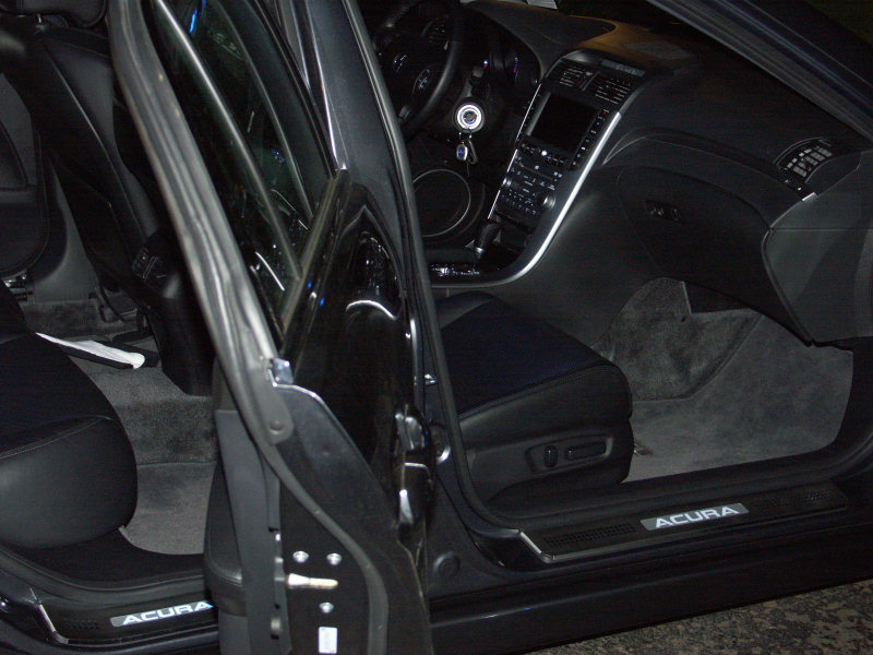
Directions to install the Illuminated Door Sills created by Supercomputer (member of AcuraZine.com) on a 2005 Acura TL
Passenger Side Install
Main install page
01) Remove front wire routing cover. Be careful when removing, it is easy to break the plastic
clips. After I removed the cover, I pulled some of the clips out of the car to make
the reinstall easier.
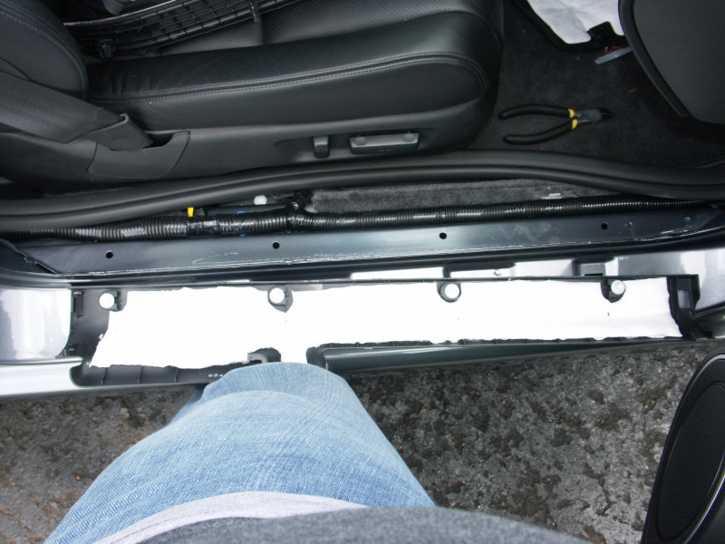
02) Rear cover removed.
03) Rear cover (bad lighting)
04) B Pillar cover removed (there are two clips at the bottom, on in front and one in rear). It is easy
to remove...apply pressure to the bottom center of the pillar, grab a side and bend to get it
off the round clips. There up top by the seat belt it just snaps in, so it easily pulls out.
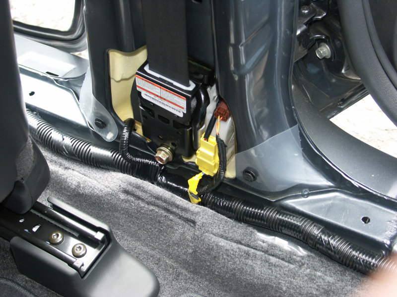
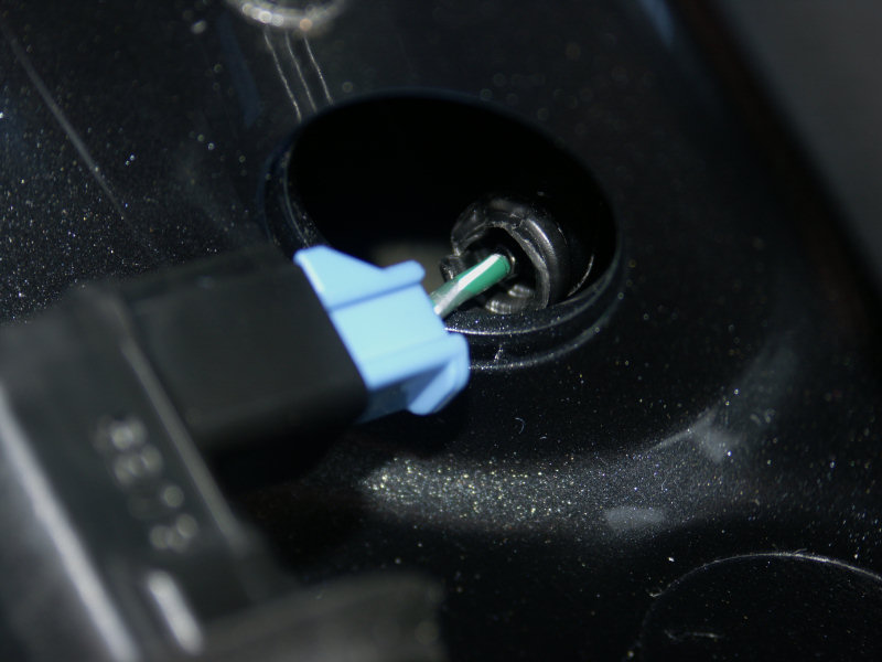
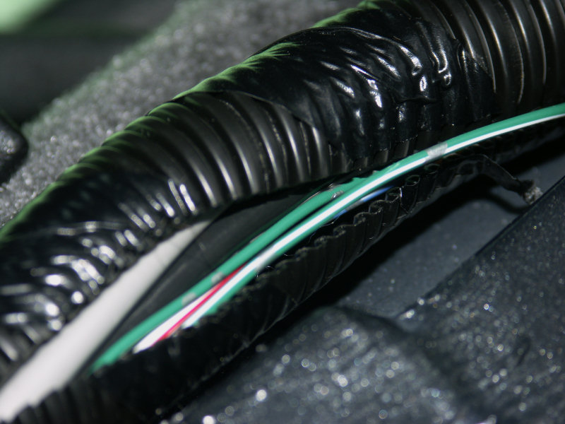
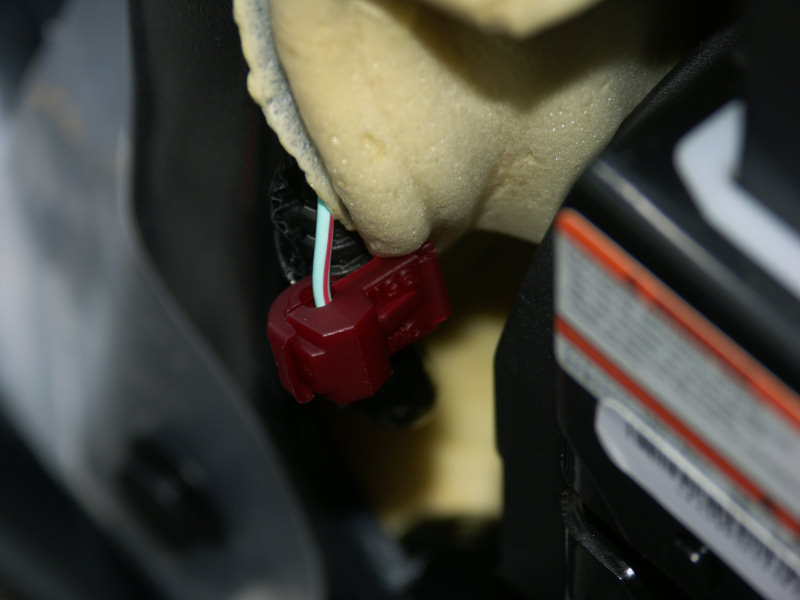
05) Rear door switch (green with small white stripe)
06) closeup of bottom of B pillar
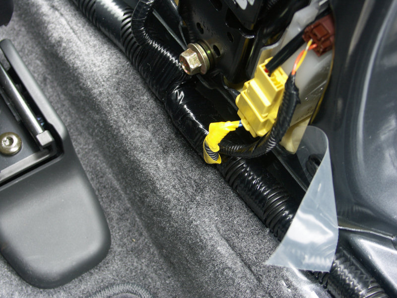
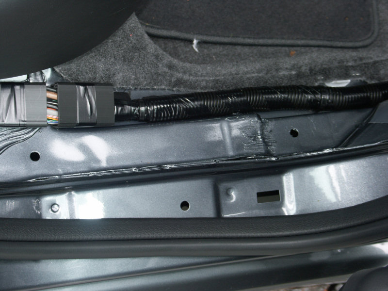
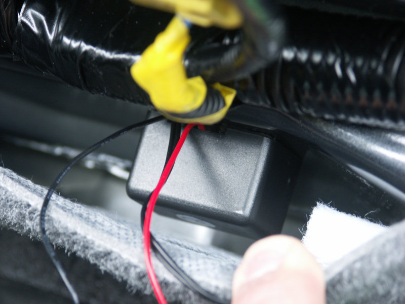
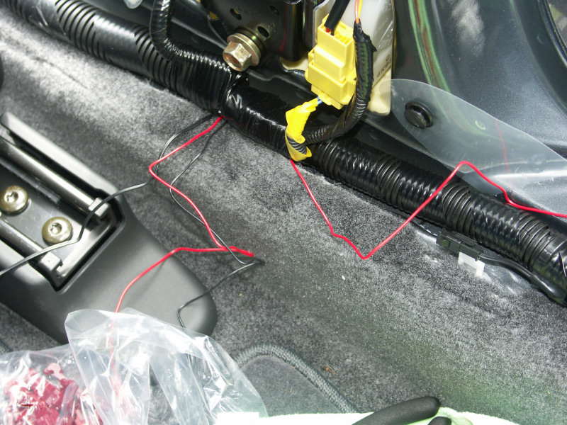
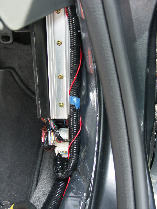
07) We need a place to put the voltage regulators (1 inch square boxes with wires). There is a
gap between the carpet and the frame of the car...perfect for our usage.
08) As you can see on the right, the frame bends in about an inch and there is the space we will use.
09) 1 voltage regulator installed
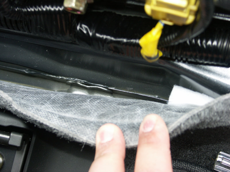
10) Install the rear sill and start to route the wire coming from it. As I have mentioned on the forum
my frame has spots where there are dips big enough to route a wire. If you don't have these on
your frame, you can still route the wire over the weld edge, just be sure to try and smooth the edge
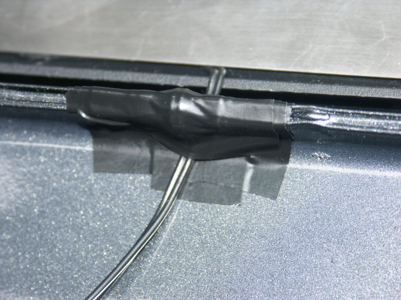
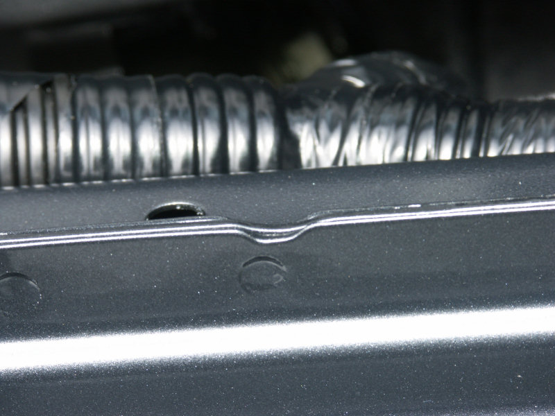
like I did. First put electrical tape over the area. On the side that will be exposed to the outside
don't put the tape down too far, this way it will be covered by the weather stripping and hidden.
After applying the tape, the area is now smoother then before and I am less worried about the wire
getting damaged.
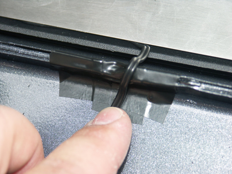
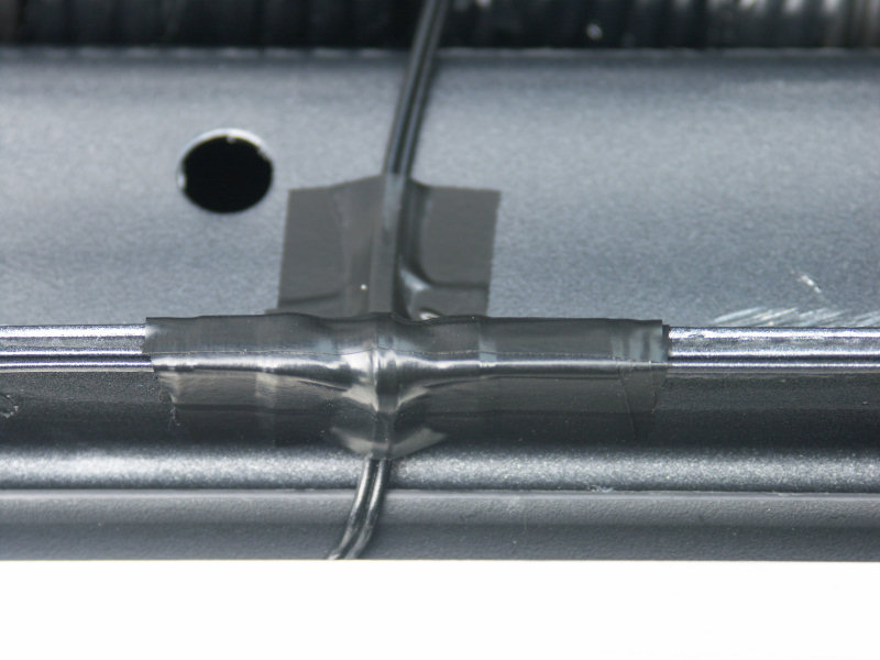
11) Tape the wire in place so that in the future you won't have problems when removing the weather
stripping.
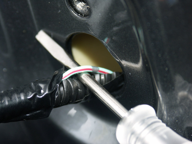
12) Now it is time to get the negative/ground ready for the rear sills. Carefully cut the tape
on the wire loom and look for our green wire with the white stripe. There isn't a lot of
slack on the wire, but pull it out a little so that we can tap into it.
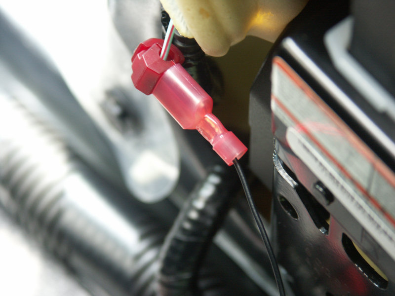
13) 3M T-Tap (18-22 gauge) installed on rear door switch wire & male disconnect on end of black
wire coming from voltage regulator.
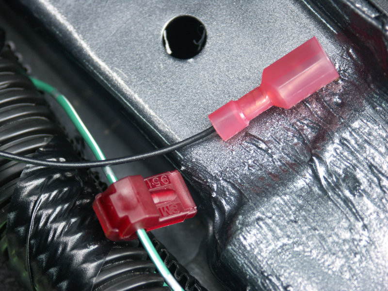
14) Connect them together. I then took them and tucked them into the gap right beneath them.
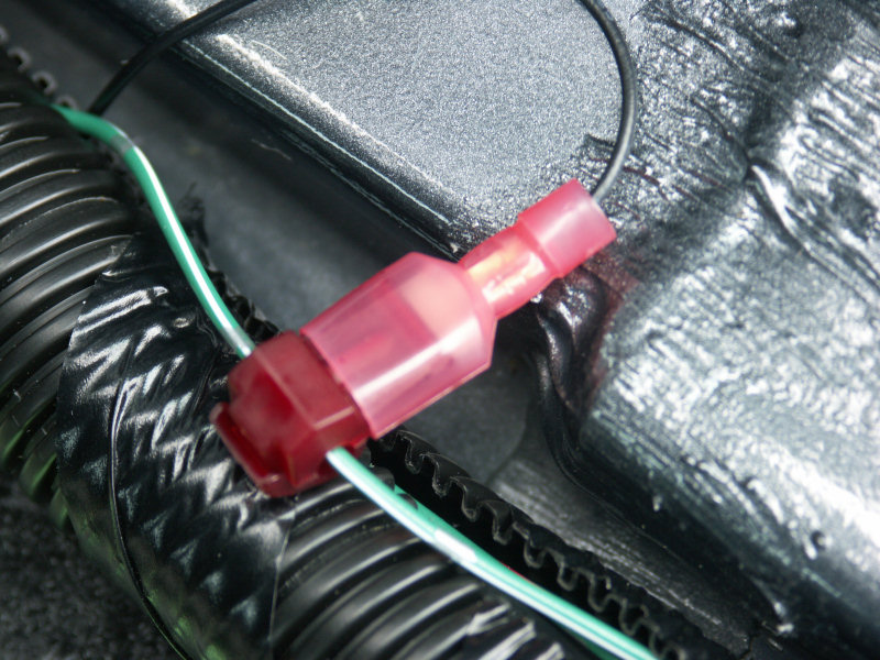
15) The rear is done for now and only needed constant power, which we will get to later.
Now install the voltage regulator for the front sills right next to the other one.
16) As you can see the voltage regulators fit nicely and don't buldge out or anything.
17) Front passenger switch (in the directions provided it says this wire is light green with
a red stripe, but to me this looks more like white with a red stripe). There is plenty
of slack on this wire and wire loom so we will tap into it here instead of on the floor.
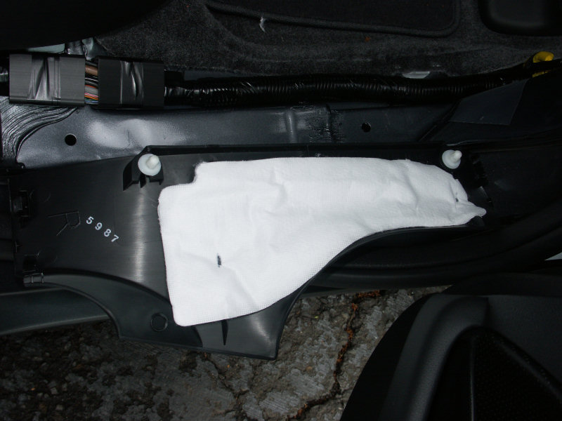
18) Pull out the insulation foam and find the wire loom for the switch. Carefully cut the tape
on the loom and pull the wire out so we can tap into it.
19) Front passenger switch wire tapped and connected to the ground from the voltage regulator
20) Here is the dip in the frame welding that I will use for the front.
21) Place tape over the dip to smooth the edges, place the wire it it and cover with tape.
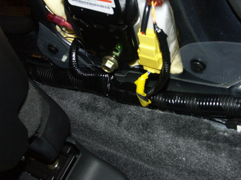
22) Tape the wire down so it can get into up to the wire loom, and then run it back to the B pillar.
23) Here is the clip behind the glove box which holds the plugs containing the 12v constant power
we need to tap into. Squeeze on the side with a pair of needlenose pliers or a flathead screwdriver
and wiggle it until the clip is out of the hole.
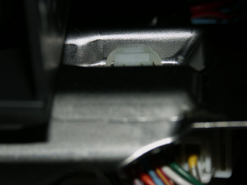
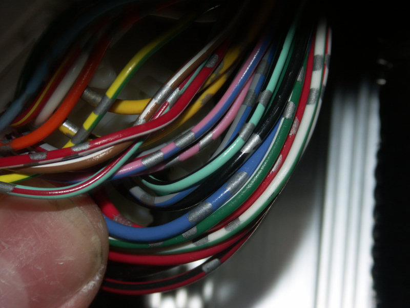
24) The plugs are now loose, here is a closeup of the wires. We will be using the 9th wire from the
right, the gray & blue striped wire next to the black/white one.
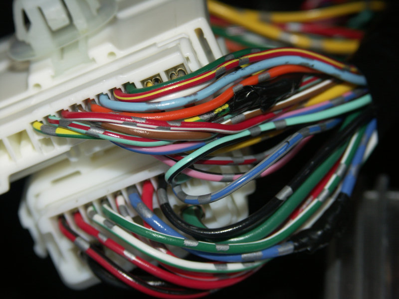
25) Here is the gray & blue striped wire in the middle. The two taped up wires are the wires I
incorrectly tapped using the original directions provided, and by mistaking the solid blue with
silver paint for what GRich4u meant by "gray & blue".
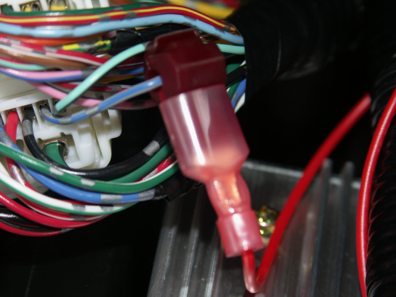
26) 12v tapped and connected
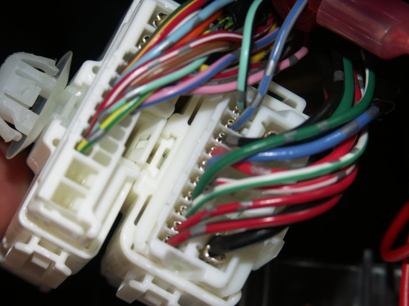
27) Another closeup of the set of plugs. Our wire is in the one on the right, 2nd from the top.
28) Snap the plus back into place and route the wire along with the other wires in the area.
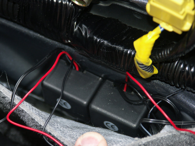
29) The last connection you need to make is to connect the red wires from the voltage regulators to
the wires we just hooked to constant 12v (there are no pictures of this since you just need to
install another T-Tap and connect the wires together.
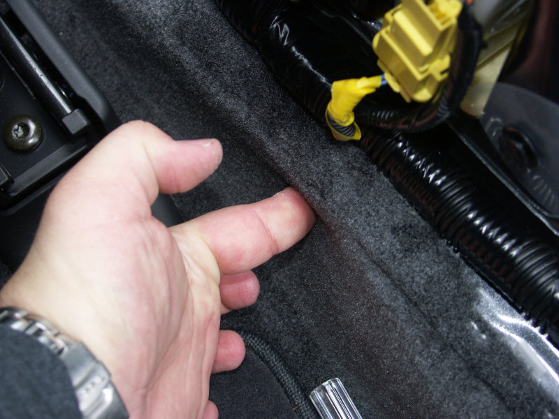
The B pillar area is finished. I hid all extra wires under the carpet in the space where I put the
voltage regulators.
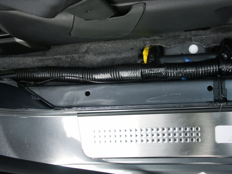
30) Now install all the wires covers again. The proper order is the B pillar first, then the front/rear
areas, and the kick panel last. We are now done.
31)
32)
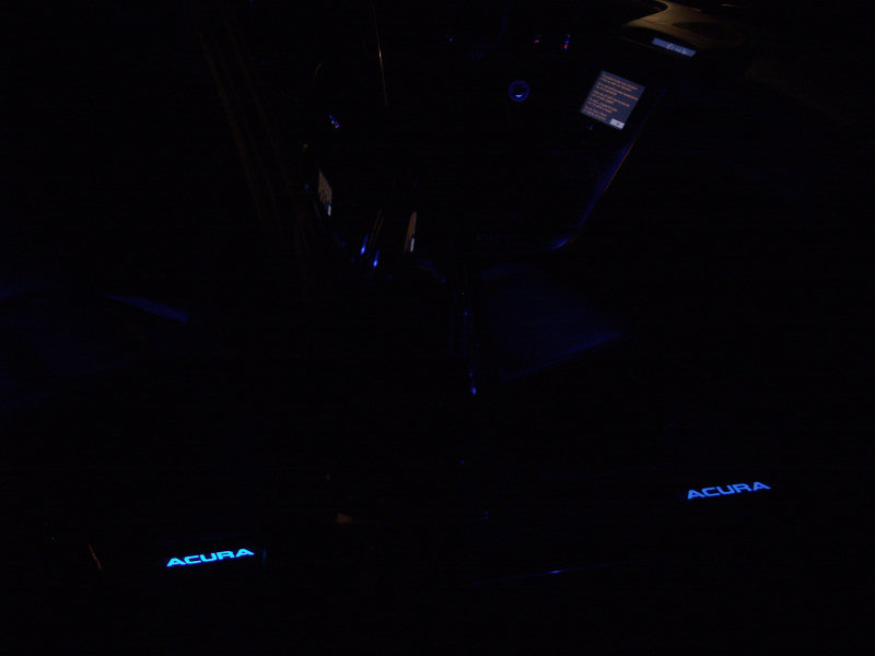
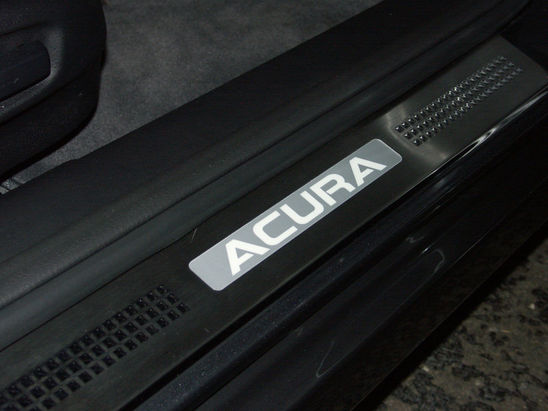
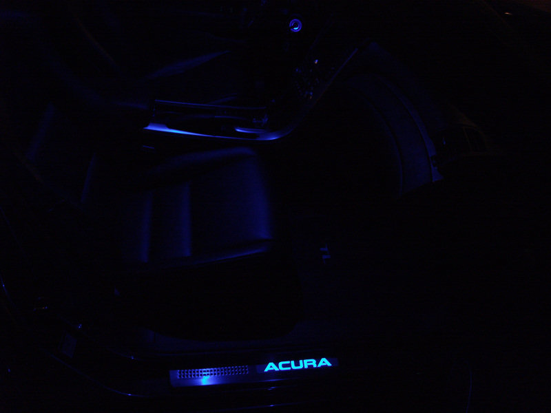
33) Here is what you've all been wating for...very nice!

34) Front sill with 9 led door light.

35) Front sill with interior 9 led blue lights.
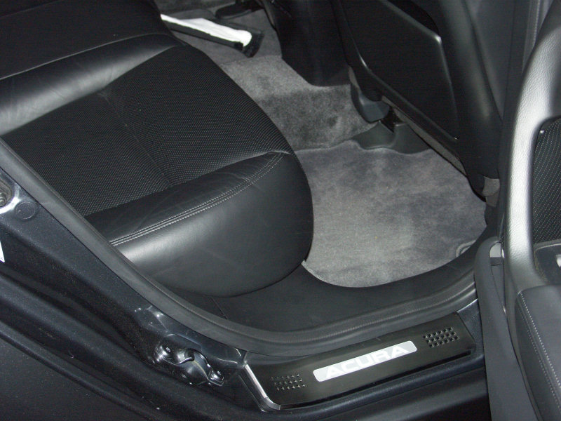
36) Front and rear sills by themselves. Note that the rear is a little brighter, but
my guess is that is probably because the area is smaller.
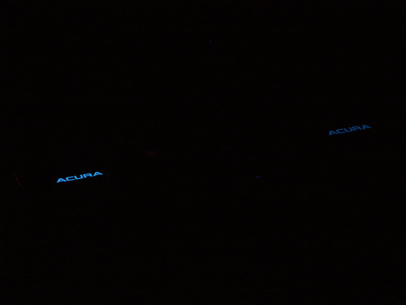
37) Front and rear sills with interior.